Making a headset capable of real-time eeg, sound synthesis and machine learning is a rather daunting task with many steps involved. Instructions on how to build such a headset along with technical information regarding the original Inhibition prototype and its future incarnations are given below. Resources, (pcb, schematics and code) are also available in github.
electrodes and electrolyte
Largely, there are three kinds of electrodes: ‘wet’, ‘dry’ and ‘active’ ones. For the original Inhibition headset I have used ‘wet’ electrodes (Ambu Neuroline cup electrodes, in particular). I have also experimented with both wet and dry electrodes by Florida Research Instruments: I noticed some oxidation on wet ones after use and I don’t really like the dry ones anyway. Note however that if you want to measure eeg in parts of the head with hair, dry or active electrodes are the only way to go (unless shaving the head is an option). Wet electrodes require adequate skin preparation and some special gel to increase skin conductivity. I have used with very good results some gels by OneStep as well as the Spectra 360 electrolyte gel by parker laboratories. I have no experience at all with active electrodes. You can find out more about electrodes and electrolytes here and here.
Electronics
For Inhibition I have designed my own schematics after considering various open-source designs, research papers and academic resources (e.g. this, this, this, this, this, and this). None the designs I have found was good or cheap enough for Inhibition so I came out with this:
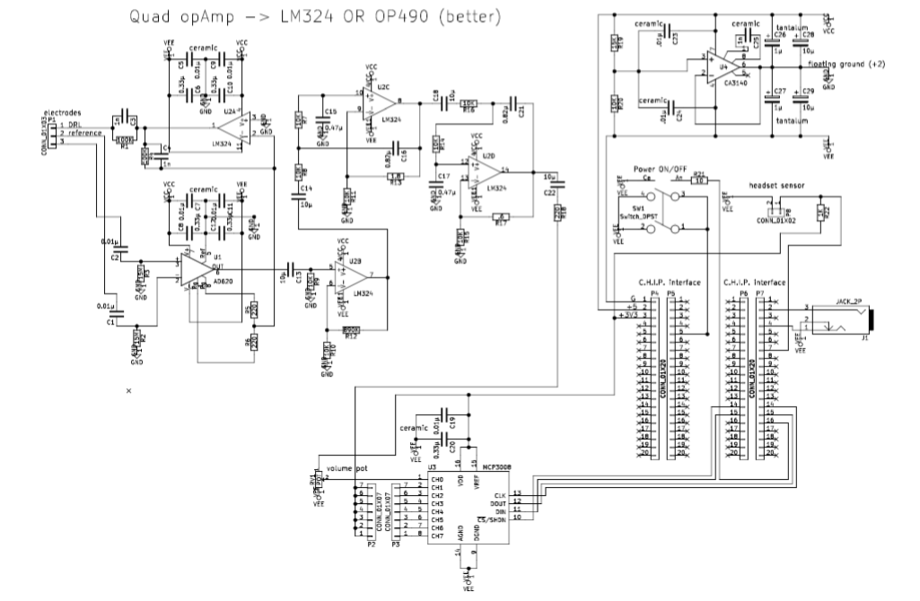
(also available here as pdf). I am sure that there is a lot of room for improvements, still this circuit more or less achieves all my requirements:
- 5V single supply (so that it may be battery operated)
- excellent performance at the 1-20Hz frequency range
- high noise and electric hum rejection
- moderately cheap (so that it is suitable for workshops)
- stackable (so that more than one pcbs could be used for more eeg channels)
- easy to solder (it is workshop material after all)
- easy to embed into a wearable device
The circuit comprises a first amplification stages, a Driven-Right-Leg (DRL) circuit, a hi-pass filtering-amplification stage, two low-pass filters, a power supply circuit, analogue-to-digital conversion and circuity relevant with the single-board computer in use (a headset ON/OFF switch, an ON/OFF switch, a LED, a pot to control the volume and an audio out jack). The most important stages are discussed below:
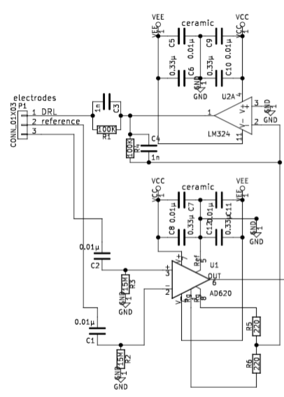
The reference and the ‘hot’ electrode drive two passive HiPass filters the output of which is fed to a AD620 instrumentation amplifier (datasheet here). R5 and R6 set the gain of AD620 as follows: G = (49.4kΩ / (R5+R6) ) + 1. Note, however, that values below 1K make no real difference since the chip can’t amplify the signal that much with just a 5V supply. If you change the supply you will most likely have to change the R5, R6 as well as R12 to avoid clipping the signal. A copy of the output is then fed into the inverting input of the first stage of a quad op-amp and fed back to the skin using the DRL (Driven-Right-Leg) electrode. This ensures that a big proportion of the electrical hum and the environmental electrical noise that is ever-present in our bodies is cancelled out so that we are left with a moderately clean eeg signal. The quad op-amp could be a high-precision and low-noise OP490 (datasheet) or the much cheaper LM324 (datasheet). In the original Inhibition headset I have used OP490, but for workshop purposes I prefer the LM324 which is significantly cheaper. Bypass capacitors are provided for both chips so that any spikes are filtered out.
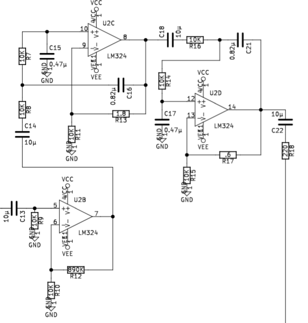
Next comes a HiPass filter-amplifier with a cut off frequency at 1.6Hz and a gain of 89 (890K/10K), and two 2-pole LowPass filters with a cut-off frequency at app. 19Hz. Everything is ac-coupled using 10uF capacitors (I have used non-polarised electrolytic capacitors). Now I have to admit that I don’t really understand that part of the circuit very well. I took the design for the individual LowPass filters from this book (pages 1986-7). What happens if you tinker with R13 and R17 is quite interesting: with any value above 7-8Ohm you get no signal at all – everything is blocked out; with values of app. 3-8 Ohms for R13 and 1-8 for R17 you just get massive self-oscillation; values of 0-3 Ohms for R13 and 0-1 for R17 the behaviour is correct. I am not really sure why this circuit behaves like that but as long as the behaviour is correct I don’t really mind.
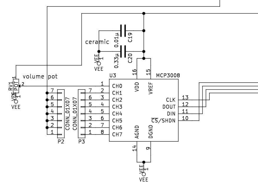
This stage is rather straightforward: the signal ends up to a set of pins so that with a jumper it can be rooted to any of the ADC’s input channels (this way when using multiple pcbs stacked on top of each other it’s possible to route the individual signals to different channels). This part of the circuit also shows some bypass capacitors and the routing to the digital interface (this chip can be read using the SPI protocol).
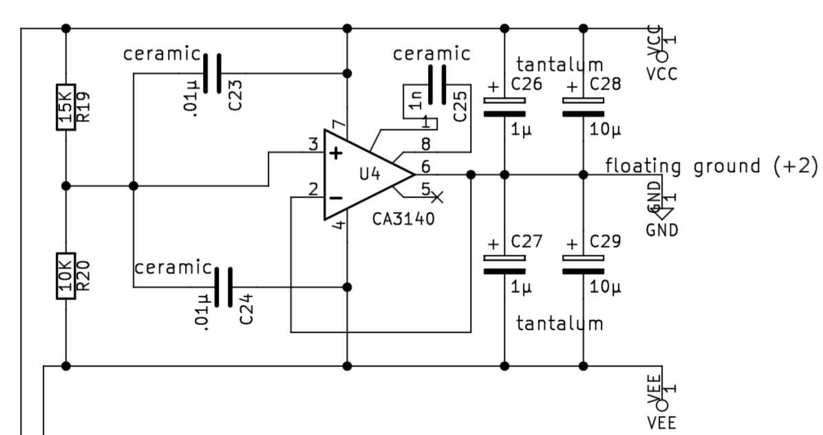
This part of the circuit creates a ‘floating ground’ between the +5V supply and the G. Both OP490 and LM324 swing up to ~1.4 volt below the positive supply and up to ~0.5 above the negative; with a 2V floating ground it’s (at least theoretically) possible to achieve a ±1-1.5V swing.
Pcb
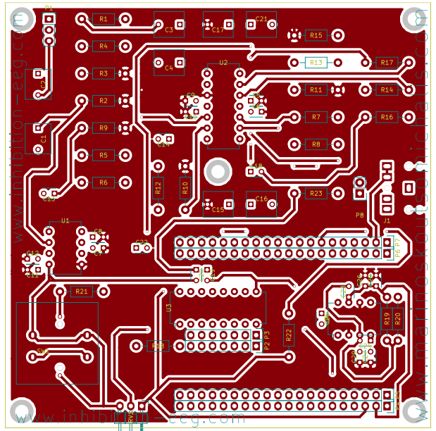
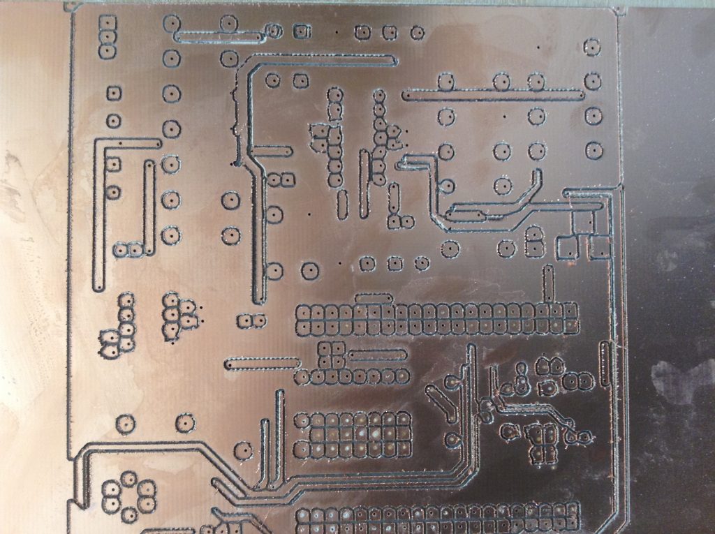
The first version of the pcb looks like this:
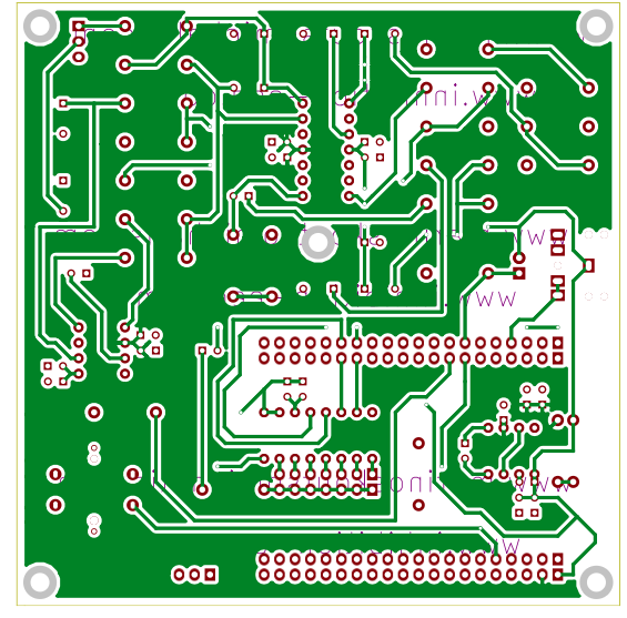
Note however that there are a couple of errors in this design. You need to cut pin 8 and bridge it to another as shown in the image below (as I’ve found out later on, the XPIO pins in the C.H.I.P. don’t provide enough amps to drive a led..) and to completely cut pin number 7 to its right if you use the particular switch I’ve used (this switch bridges its pins internally so that it will keep pin 7 permanently connected with the pwr pin which will result in the C.H.I.P. automatically booting again after a shutdown). These errors I have corrected in the schematic and will be sorted out in the next version of the pcb which I will upload soon.
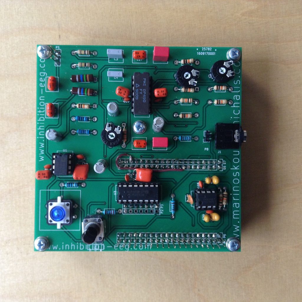
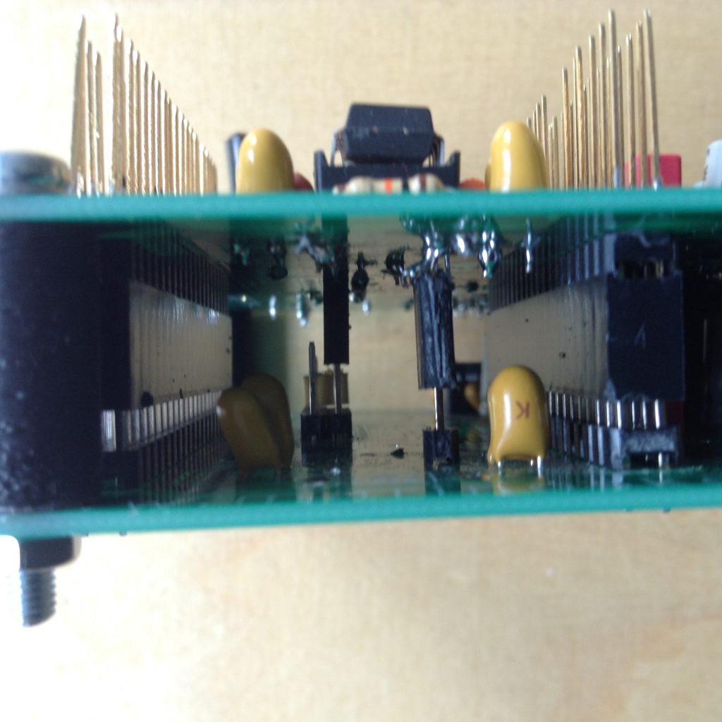
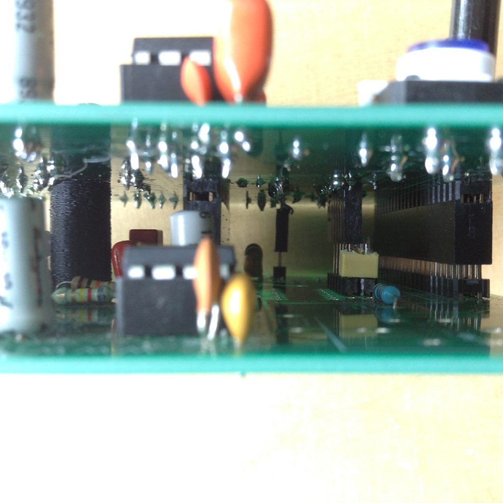
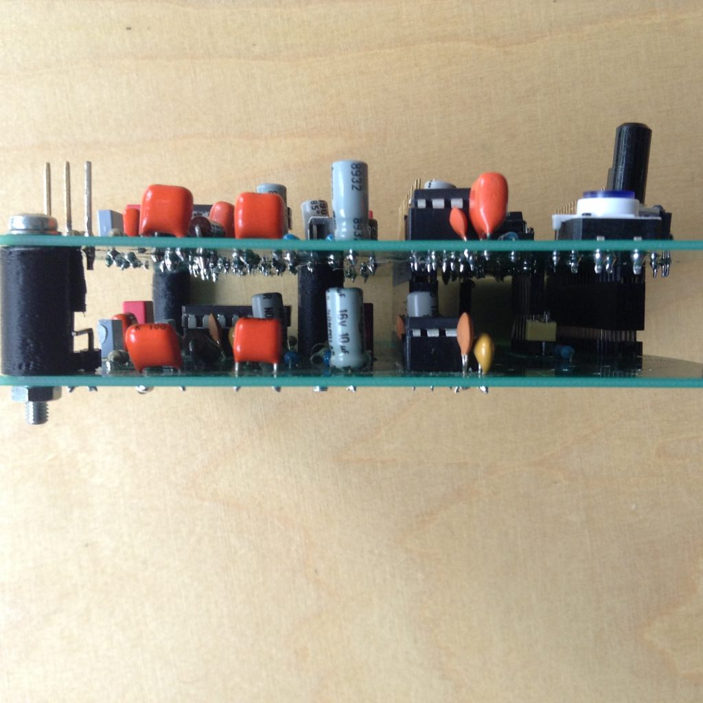
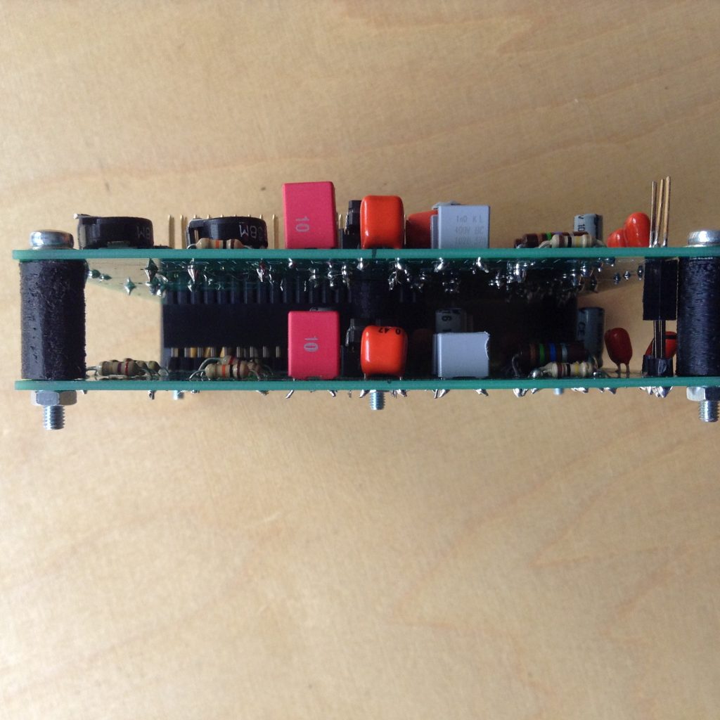
The pcb is designed to be stackable so that up to 7 pcbs maybe be used with the same single-board computer. To use more than one pcb you need to use stackable pins as shown in the images below. The DRL and the reference electrode are shared in all pcbs. The floating ground should be also shared: completely omit the power supply circuit from the rest pcbs and solder stackable pins in the place of the opamp’s pin 6. The final output should be routed to different channels on the ADC using stackable pins and jumpers. Note that all the rest pcbs should omit some components: the MPC3008 chip, the entire power supply circuity (you can keep the tantalum capacitors if you want for bypass), the pot, the switch, the LED, the pins for the headset ON/OF sensor and the audio jack. To make sure the pcbs are well fixed I have used 3d-printed cylinders and M3 screws.
Then the C.H.I.P. can be stacked on top like a shield as shown here:
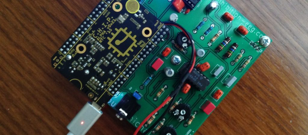
The pcb could be made significantly smaller, but this particular version is also adequate for CNC-milling and is also easy to solder.
Setting-up C.H.I.P.
There are single-board computers out there for every taste. For the original Inhibition prototype I have use a C.H.I.P. because it is very cheap and very light, it has a low power consumption and it includes a step-up transformer and a battery charger. I think it’s ideal for such a project, albeit it is not as powerful as other competitive boards.
UPDATE: There is a first installation pack I use in the workshops that automates as far as possible the installation procedure, also installing the basic vanilla code I use in the Inhibition workshops. You might want to consider using it, note, however, that it will also compile and install code you might not want to use, thus making the procedure unnecessarily longer than needed. If you encounter any problems, it could be that sth’s broken so try the manual way instead. Steps are as follows:
- Flash Debian 4.4 software using the flasher. I prefer the headless version.
- Log in to the system over the serial, e.g. using screen it should be sth like: screen /dev/tty.usbmodemXXXX – replace XXXX with the actual port)
- become root with su (password is chip)
- connect to the internet wirelessly: nmcli device wifi connect “XXXX” password “XXXXX” ifname wlan0 – replace XXXXs with SSSID and Password respectively
- apt-get update && apt-get upgrade && apt-get -y install git
- git clone https://github.com/Inhibition-EEG/chip_setup.git
- cd chip_setup
- chmod +x ./install_script.sh
- ./install_script
All the rest should be carried automatically – note that YOU DO HAVE TO INTERACT once, the installation for jack will ask you if you want to enable real-time priority. You probably want to answer yes here.
Documentation on the C.H.I.P. is available here.
UPDATED Manual installation procedure for the workshop pack.
- Flash Debian 4.4 Headless using the flasher.
- Log in to the system over the serial. e.g. using screen (password is chip):
screen /dev/tty.usbmodemXXXX - connect to your local network SSID with passord PASS
sudo nmcli device wifi connect “SSID” password “PASS” ifname wlan0 - get the ip address of the device
ip addr - once done, quit screen, preferably connect CHIP to a power supply (although the computer’s usb should be fine too), disconnect and connect again using ssh
ssh chip@192.XXX.XXX.XXX - become root (password is chip)
su - update
apt-get update - upgrade
apt-get -y upgrade - install the necessary packages (select ‘yes’ when asked)
apt-get -y install jackd2 python-dev alsa-base alsa-utils libicu-dev libasound2-dev libsamplerate0-dev libsndfile1-dev libreadline-dev libxt-dev libudev-dev libavahi-client-dev libfftw3-dev cmake git gcc-4.8 g++-4.8 libjack-jackd2-dev libsndfile1-dev clang sox python3 python3-setuptools libfann-dev - download/install the library for controlling the gpios
wget -O /usr/local/bin/gpio.sh http://fordsfords.github.io/gpio_sh/gpio.sh - download the workshop code bundle
git clone https://github.com/Inhibition-EEG/chip_setup.git
git clone https://github.com/Inhibition-EEG/audio_synthesis.git
git clone https://github.com/Inhibition-EEG/neural_net.git
git clone https://github.com/Inhibition-EEG/read_spi.git - setup jack
cp chip_setup/system.conf /etc/dbus-1/system.conf
chmod 644 /etc/dbus-1/system.conf
cp chip_setup/etc_security_limits.conf /etc/security/limits.conf
groupadd realtime
usermod -a -G realtime root
usermod -a -G realtime chip - install locales (in at least one occasion couldn’t compile SC without doing that!!!)
apt-get install locales
locale-gen en_US en_US.UTF-8 - configure the locales – on the list selected everything that starts with en_US, and on the second list select the UTF ones
dpkg-reconfigure locales - install supercollider
git clone –recursive git://github.com/supercollider/supercollider.git supercollider
cd supercollider
git submodule init
git submodule update
mkdir build
cd build
export CC=/usr/bin/gcc-4.8
export CXX=/usr/bin/g++-4.8
cmake -L -DCMAKE_BUILD_TYPE=”Release” -DBUILD_TESTING=OFF -DSUPERNOVA=OFF -DNOVA_SIMD=ON -DNATIVE=OFF -DSC_ED=OFF -DSC_WII=OFF -DSC_IDE=OFF -DSC_QT=OFF -DSC_EL=OFF -DSC_VIM=OFF -DCMAKE_C_FLAGS=”-mfloat-abi=hard -mfpu=neon” -DCMAKE_CXX_FLAGS=”-mfloat-abi=hard -mfpu=neon” ..
make
make install
ldconfig - install sc3-plugins
cd ../..
git clone –recursive https://github.com/supercollider/sc3-plugins.git
cd sc3-plugins
mkdir build
cd build
cmake -DSC_PATH=/home/chip/supercollider ..
cmake –build . –config Release –target install - install sc dependencies
cp -rf /home/chip/chip_setup/sc_dependencies/* /usr/local/share/SuperCollider/Extensions/ - create inhibition dir
mkdir /home/chip/Inhibition - audio synthesis code
cp -rf /home/chip/code/audio_synthesis/* /home/chip/Inhibition - neural network
cd /home/chip/neural_net
cmake ..
make
cp -rf Install/* /home/chip/Inhibition - adc
cd /home/chip/read_spi
mkdir build
cd build
cmake ..
make
cp -rf Install/* /home/chip/Inhibition/ - copy run script
cd /home/chip/Inhibition
cp /home/chip/chip_setup/run.sh /home/chip/Inhibition/run.sh
chmod 777 /home/chip/Inhibition/run.sh - init, clean up, etc
cp /home/chip/chip_setup/rc.local /etc/rc.local
chmod 755 /etc/rc.local
cp /home/chip/chip_setup/etc_cron.d_ieeg /etc/cron.d/ieeg
cp /home/chip/chip_setup/halt /etc/init.d/halt
chmod 755 /etc/init.d/halt
Other notes on software:
For sound you need to set-up jack, too
sudo apt-get install jackd2
then, in /etc/dbus-1/system.conf add this at the very end (just before the </busconfig>)
<policy user=”root”>
<allow own=”org.freedesktop.ReserveDevice1.Audio0″/>
</policy>
and if you also plan to use a usb soundcard)
<policy user=”root”>
<allow own=”org.freedesktop.ReserveDevice1.Audio1″/>
</policy>
you can set up RT priority for jack by putting these in /etc/security/limits.conf :
@realtime – rtprio 99
@realtime – memlock unlimited
and then as root do these:
groupadd realtime
usermod -a -G realtime root
usermod -a -G realtime chip
you can then launch jack like this (as root)
export DBUS_SESSION_BUS_ADDRESS=unix:path=/run/dbus/system_bus_socket
export DEVICE=:0
jackd -P75 -dalsa -Phw:0 -p2048 -n3 -s -r44100 &
(note that you might need to try out bigger block sizes to avoid glitches on the expense of latency – block sizes have to be powers of two. if latency is an issue you’d better use an external sound card and possibly a more capable single-board computer)
In the original Inhibition prototype I do all sound synthesis with the SuperCollider programming environment. To set-up SuperCollider:
- sudo apt-get install python-dev alsa-base alsa-utils libicu-dev libasound2-dev libsamplerate0-dev libsndfile1-dev libreadline-dev libxt-dev libudev-dev libavahi-client-dev libfftw3-dev cmake git gcc-4.8 g++-4.8 libjack-jackd2-dev libsndfile1-dev
- git clone –recursive git://github.com/supercollider/supercollider.git supercollider
- cd supercollider
- git submodule init && git submodule update
- mkdir build && cd build
- export CC=/usr/bin/gcc-4.8
- export CXX=/usr/bin/g++-4.8
- cmake -L -DCMAKE_BUILD_TYPE=”Release” -DBUILD_TESTING=OFF -DSUPERNOVA=OFF -DNOVA_SIMD=ON -DNATIVE=OFF -DSC_ED=OFF -DSC_WII=OFF -DSC_IDE=OFF -DSC_QT=OFF -DSC_EL=OFF -DSC_VIM=OFF -DCMAKE_C_FLAGS=”-mfloat-abi=hard -mfpu=neon” -DCMAKE_CXX_FLAGS=”-mfloat-abi=hard -mfpu=neon” ..
- make
- sudo make install
- sudo ldconfig
- cd ../..
- sudo mv /usr/local/share/SuperCollider/SCClassLibrary/Common/GUI /usr/local/share/SuperCollider/SCClassLibrary/scide_scqt/GUI
- sudo mv /usr/local/share/SuperCollider/SCClassLibrary/JITLib/GUI /usr/local/share/SuperCollider/SCClassLibrary/scide_scqt/JITLibGUI
and if you also want the sc plugins (I do)
- git clone –recursive https://github.com/supercollider/sc3-plugins.git
- cd sc3-plugins && mkdir build && cd build
- export CC=/usr/bin/gcc-4.8
- export CXX=/usr/bin/g++-4.8
- cmake -DSC_PATH=/home/chip/supercollider ..
- make
- sudo make install
For my particular set-up I also needed some other tools:
- clang compiler (sudo apt-get install clang)
- sox for NRT sound processing and conversion (sudo apt-get install sox)
- gpio.sh script to easily access the GPIO pins: (sudo wget -O /usr/local/bin/gpio.sh http://fordsfords.github.io/gpio_sh/gpio.sh)
- python 3 (sudo apt-get install python3 python3-setuptools python3-numpy python3-scipy)
- fann (sudo apt-get install libfann-dev)
NOTE: You don’t have to do the following anymore, as long as you use the latest Debian, it’s enough to add this to rc.local
| mkdir -p /sys/kernel/config/device-tree/overlays/spi |
| cat /lib/firmware/nextthingco/chip/sample-spi.dtbo > /sys/kernel/config/device-tree/overlays/spi/dtbo |
(—
then you need to install a special kernel that enables SPI so that you can retrieve the data from MPC3008 chip:
- wget https://dl.dropboxusercontent.com/u/48891705/chip/4.4.11w1TH%2B.tgz
- sudo bash
- cd /
- tar -xzf /home/chip/4.4.11w1TH+.tgz
- cd /boot
- rm zImage
- cp vmlinuz-4.4.11w1TH+ zImage
—-)
this is how my /etc/rc.local looks like:
source /usr/local/bin/gpio.sh
gpio_export CSID5
gpio_direction CSID5 out
gpio_output CSID5 1
gpio_export XIO_P1
gpio_direction XIO_P1 in
This turns the LED ON on start-up, enables XIO_P1 for reading (this is where the headset ON/OFF switch is plugged)
if you also want to have the LED turned OFF on shutdown, put this in /etc/init.d/halt (before anything else):
gpio_output CSID5 0
to run jack and sclang on startup put something like this in e.g. run.sh
#!/bin/sh
export DBUS_SESSION_BUS_ADDRESS=unix:path=/run/dbus/system_bus_socket
export DISPLAY=:0
PATH=$PATH:/usr/local/bin
cd /home/chip/Inhibition
jackd -P99 -dalsa -Phw:1 -p8192 -n3 -s -r44100 &
sleep 15
sclang main.scd # replace main.scd with the file having your code
exit 0
then you need to (as root): chmod +x run.sh
and schedule it for execution on startup with crontab:
- (as root) crontab -e
- add the following to the end: @reboot /bin/bash /home/chip/run.sh
Reading the eeg signal
For the original headset I have coded a C++ utility that reads a several-second chunk of two-channel eeg activity and writes it in a 2-channel wav file for subsequent analysis. I have also coded a utility to read the potentiometer values that can be then used to control e.g. the overall volume. The code for both can be found in github. In the original signal the EEG signal is analysed using FEUtil (Feature Extraction Utility) which is the only part of the project I cannot publish. FEUtil is part of project So.D.A. which I have co-developed when working as a fellow researcher in the University of Turin.
sound synthesis
For sound synthesis I have used the programming environment SuperCollider. The code for the algorithmic sound generation used in the original headset can be found in github. The code is designed so that it attempts to constantly ‘detune’ one’s neurophysical activity. If for example the system monitors a frequency of 9 as the dominant frequency generated by the brain, the generated sound will use a combination of pannings, frequency beats and intra-modulation to shift this frequency to 10 or 8. When this change is registered, the system will attempt to modulate it again, and so on. The original code can be found in github.
Machine Learning
For my purposes I have coded a simple c++ utility that creates a ‘shortcut’ artificial neural network, trains it with back-propagation and uses it. The code can be found the github under the ML (c++) directory. The utility works like this:
- neural_net create -> creates a new 5-layer neural network and writes its configuration to disk
- neural_net train file.with.train.data -> reads the neural network from disk and trains it with the data provided; data should be in a file and should be formed as follows:
- first line: number of input-output sets, number of inputs, number of outputs (in my code this is always 1,16,8)
- neural_net train use data data data (16 distinct numbers should be fed) -> given 16 input scalars it will outputs 8 scalars
note that the network expects inputs in the 0,1 range – else it will never train properly.
For the original Inhibition headset I follow this idea:
- actions are a set of indices (8) use I use to select the audio parameters from arrays of possible discrete values
- features are spectral features extracted from the eeg signal using FEUtil
- in each iteration the algorithm first reads and analyses the signal and then calculates the audio parameters using neural_net. I’ve also added some degree of randomness here to avoid feedback loops or static behaviour.
- the analyses of the eeg signal also produces a value for current ‘pitch’, that is the dominant frequency of the waves emitted by the brain.
- the algorithm determines the ‘target’ frequency and pass this to the audio algorithm as well
- after a few seconds the algorithm re-analyses eeg from the brain and compares the new ‘pitch’ with the previous one to assess the effectiveness of the algorithm (the main idea behind the original headset is to constantly change the dominant frequency of the waves emitted by the brain). If there is change greater than a threshold of 0.6Hz in the activity of the brain, then this configuration is considered successful – the algorithm then creates a new file with the training data and trains the network so that it ‘learns’ this particular behaviour.
Headset design
*material to be uploaded
This is great documentation. I got chuck working with Jack 2 but haven’t tried super collider. I am curious if you used a USB sound card or the pins for your adc and dac.
Hi! I’ve tried both with a usb soundcard and with the built-in dac (not with the adc though). Both work fine.